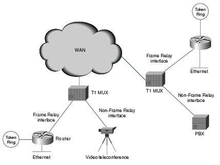
Frame Relay is a protocol for transmitting data over a wide area network (WAN). It was designed to use across ISDN interfaces but it is now used over an assortment of other network interfaces. Once one becomes a master of frame relay design and configuration, it is much easier to obtain a strong understanding of x.25, ATM, and SMDS. Frame relay operates at the physical and data link layers of the OSI model.
Frame relay is an example of packet switched technology. In a packet switched network, end stations share the network medium and available bandwidth, and packets are switched between the various network segments until the destination is reached. Packet switched network technology allows more flexibility and more efficient use of bandwidth. Frame relay is also known as the streamlined version of x.25 because of windowing and retransmission of the lost data.

Frame Relay Devices
There are two types of devices attached to a frame relay WAN, DTE, and DCE.
- DTEs (Data Terminal Equipments) are generally terminating equipments for a specific network. They are typically located on the customer's premises and include: personal computers, terminals, bridges, and routers.
- DCEs (Data Circuit-terminating Equipments) are carrier owned internetworking devices and they provide clocking and switching services in a network.
Physical layer component and link layer component connect the DTE and DCE devices. A physical layer component defines the electrical, functional, mechanical, and procedural specifications while a link layer component defines the protocols.
Frame Relay Network Subinterfaces
Frame relay network subinterfaces divide a single frame relay interface into multiple logical interfaces. A frame relay network subinterface addresses point to point and multiple points.
- A point to point frame relay network subinterface can have only one DLCI associated with it and it does not use frame relay map statements. If multiple point to point frame relay network subinterfaces are configured for a single router and each frame relay network subinterface has an IP address assigned to it, each IP address must be assigned from a different network or subnetwork address space.
- Multiple points frame relay network subinterface can have multiple DLCIs assigned to it. They share many of the characteristics of a physical frame relay interface and can be used with the frame relay map statements.
The frame relay DLCI command is used to assign specific DLCIs to specific frame relay network subinterfaces. Without the frame relay network interface DLCI command, all DLCIs are assigned to the physical interface. If a frame relay switch network subinterface addresses only 10 DLCIs to a router and only seven of the DLCIs are overtly assigned to existing subinterfaces on the switch, remaining DLCIs will be automatically assigned to the physical interface.
Frame Relay Switch
You can convert a Cisco router with multiple serial interfaces into a frame relay switch with minimal configuration. The commands for configuring a router as a frame relay switch are:
At global configuration mode type:
- frame-switch(config)#frame-relay switching
At the interface mode of interface serial 1, type:
- Frame-switch (config-if) #encapsulation frame-relay
- Frame-switch (config-if) #frame-relay intf-type dce
- Frame-switch (config-if) #frame-relay route 102 interface s2 201
At the interface mode of interface serial2, type:
- Frame-switch (config-if) #encapsulation frame-relay
- Frame-switch (config-if) #frame-relay intf-type dce
- Frame-switch (config-if) #frame-relay route 201 interface s1 102
The values 102 and 201 are merely examples. The user has to select a value ranging between 16 and 1007.
Frame Relay PVCs and Class of Services
A Frame Relay Network offers several design and configuration confronts. At the network layer address level, every connection within a given frame relay network appears as if all are on the same network. For PVC based configurations, every remote network layer address will need to be mapped to a local DLCI in frame relay. Inverse ARP dynamically maps remote network layer address to local DLCIs on a frame relay DTE. Inverse ARP can only map addresses from remote frame relay devices that maintain directly connected PVC to the device performing the inverse ARP. Inverse ARP can provide a complete set of mapping in a full mash frame relay topology.
Configuring a Frame Relay Router Address Connect Broadcast
The minimum frame relay configuration on a Cisco router consists of a single command:
- Router (config)#interface serial 0
- Router (config-if)#encapsulation frame-relay
- Router (config-if)#no shutdown
With this single command, a Cisco router is ready to act as a frame relay DTE device. Once this command is typed, the interface is administratively enabled and frame relay announces the configured DLCIs to the router, inverse ARP executes to map, and remote network layer addresses to local DLCIs. The limitations of the inverse ARP can be remedied with three configuration alternatives and configure a frame relay router address connect broadcast.
- Add additional PVC between the satellite 1 and satellite 2.
- Configure frame relay map statement.
- Configure point to point subinterfaces.
Frame Relay vs ATM
Similarities between the frame relay and ATM:
- They are virtual circuit based.
- They are NBMA technologies.
- They have burst rate features.
- They have congestion avoidance techniques.
- They have traffic shaping or management techniques.
- FECN of frame relay is equivalent to the EFCI of ATM.
- BECN of frame relay is equivalent to the RRM of the ATM.
Differences between frame relay and ATM:
- Frame relay is not cell based while ATM is cell based.
- Frame relay is not asynchronous while ATM is asynchronous.
- Frame relay does not have a LANE deployment while ATM does.
- Frame relay LMI is completely different from ATM ILMI.
Related Articles


0 comments:
Post a Comment